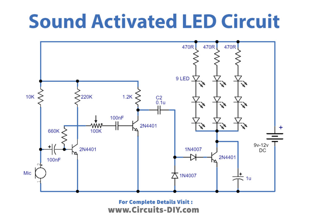
Sensitive Sound Activated LED with 2n4401 Transistors Circuit Diagram Hello, I have a driveway alarm, it beeps twice whenever a car or being passes through it. It consists of the sensor outside and the alarm signal box located indoors. I need a sound activated relay to activate when this alarm goes off. Then a relay would power a security light directed to the driveway area. Schematic of the sound activated lights circuit. Assemble the circuit on a general purpose PCB (circuit board) and enclose in a plastic cabinet. Power can be derived from a 12V, 500mA step-down transformer with rectifier and smoothing capacitor. Solder the triac ensuring sufficient spacing between the pins to avoid short circuit.
In this video, We'll teach you making a simple sound activated LED light circuit, that circuit led light with dance with the music. You can use this sound re Sound-activated LEDs are a fun and interactive way to combine audio and visuals. In this project, you will build a simple sound-responsive LED light system using an Arduino and a microphone sensor. When a sound is detected, such as clapping or music, the LEDs will light up based on the sound's intensity.
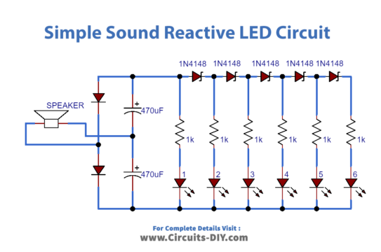
How To Make Simple Sound Activated LED Lights Circuit Diagram
As soon as the power is switched on, the microphone is powered. When it responds to sound, it emits an electrical signal. This signal is coupled by capacitor to the first transistor amplification. The amplified signals are sent to second transistor base. Second transistor drives LED to emit light. The louder the sound, the brighter the LED.

Bits4Bots - Sound to Light Control Circuit: This sound controlled lights circuit design is used to control the brightness of the lights attached to it in sync with the sound that is being captured by its microphone. This electronic circuit design is very common in disco houses, bars, parties …

Sound Activated LED with Arduino Circuit Diagram
In this tutorial, you will learn how to create a sound-activated switch using an Arduino, a Microphone Module, and an LED. This project will enable you to control a light or other device with a simple clap. Getting the Items. Arduino Uno R3 (Voltaat Version) Get Item. Microphone Module. Get Item. Clear 5mm LED (5 pack)
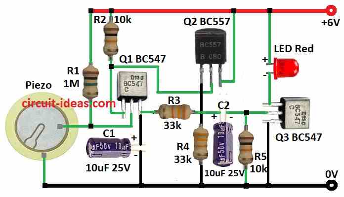
The circuit is actually a high gain MIC amplifier circuit which amplifies the external sound hitting the MIC. The amplified signal is then used to momentarily illuminate a bunch of LEDs. What does the Circuit do? Basically, this sound activated LED lamp works in the following manner:. When a sound hits the MIC, the MIC converts it into tiny electrical pulses. This is simple sound control circuit as the Whistle activated light switch circuit, that different from a little common circuit is requires high-frequency noise Such as whistle sound etc. The heart of working in this circuit is IC1 ( UM3763 ) that is designed for this particular work.