Schematic diagram of humidity sensor setup Circuit Diagram DHTxx is 4-pin device one of them is NC or no connection so, we are going to use just 3-pins. Two of them are supply pins and remaining one is output pin. The sensor may look simple, but it requires a library for handling it. The sensor consists of a thermistor, a humidity sensing device and a microcontroller embedded in a module.

sir please help me i am in bsc it third year and i have a project on smart agriculture and i want to make a project are 5 sensor in this project . how to connect the sensor of temperture humidity sensor to ardunio and aswell as on scree and with iot to thingspesk platform online . help me please . sunil10102488yadav@gmail.com. whatsapp no
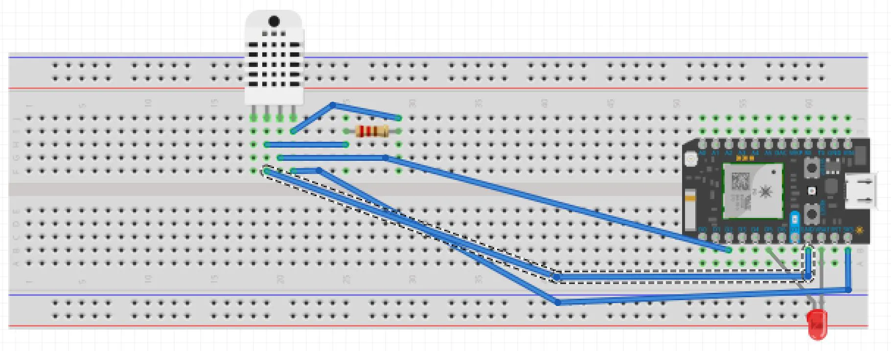
How to Set Up the DHT11 Humidity Sensor on an Arduino Circuit Diagram
Humidity Sensor: Humidity is the amount of water vapor present in the air. It can be a reliant indication of the likelihood of precipitation. The circuit is very straight forward, as you can see in the picture above. The red wire is supplying the sensor with 3.3 Volts from the Arduino board. The black wire is ground i.e. 0 Volts. The sensor does not "supply DC input." The sensor is a resistance that changes resistance as the humidity changes in moisture-content. I already explained before that the Schmitt Trigger will suddenly change considerably at a certain point when the resistance is a certain value. This causes the circuit to change states.
The simple programmable humidity sensor circuit I have explained in this article can be used for controlling or maintaining a suitable level of humidity inside a close premise. The circuit could be used in poultry farms or similar areas where humidity level becomes crucial for keeping the animals healthy. The idea was requested by Mr. Tanvir
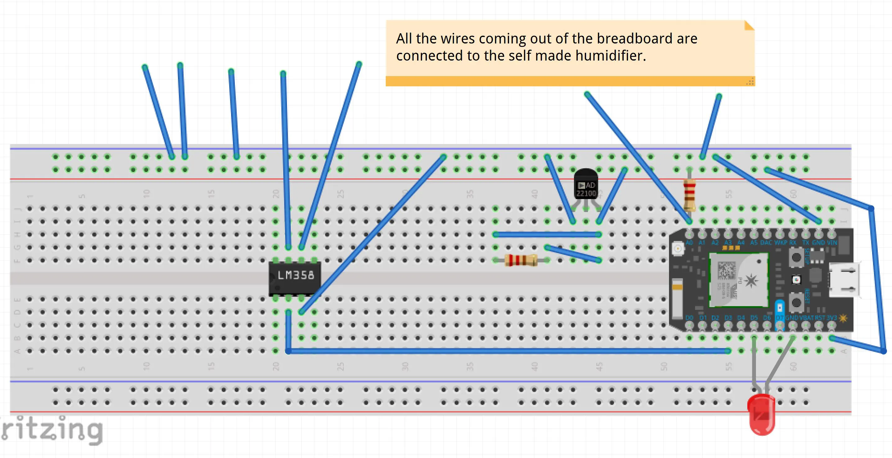
Environment Sensors Circuit Diagram
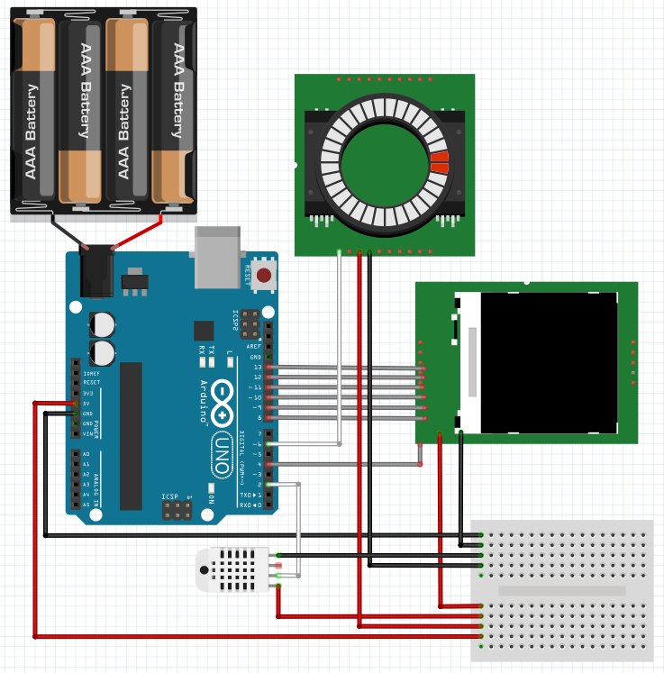
The DHT11 sensor is easy to use with the Arduino platform, and in this guide, I'll show you how to wire it up and write code to read temperature and humidity data. Before getting started, I wanted to mention that I designed this circuit (wiring diagram and code) in Cirkit Designer, which is a web-based tool for designing electronics projects. The given project measures humidity using humidity sensor and displays its value on LCD. It also compares the humidity with set humidity level and gives a message on LCD if humidity level of room is more than set level of humidity. CIRCUIT CONNECTIONS. 1. The output of DHT11 pin 2 is connected to digital pin 7 or Arduino board. The pin is How to measure temperature and humidity with the DHT11 and an Arduino. Diagrams and code are provided to display readings on an LCD or the serial monitor. Make an Arduino Temperature Sensor (Thermistor Tutorial)
